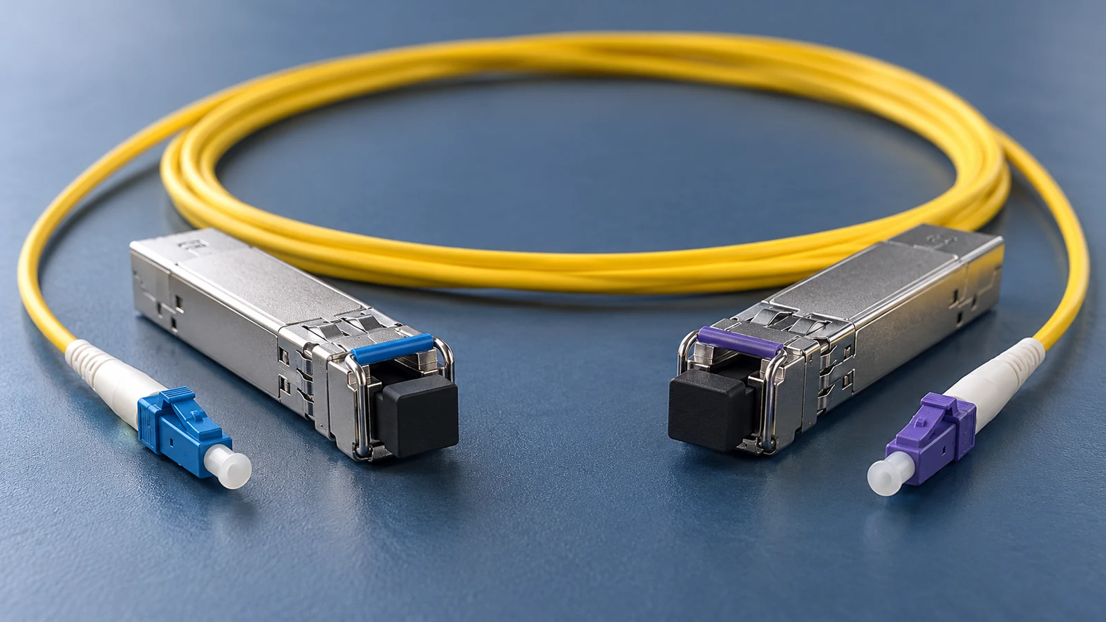
What A and B actually mean
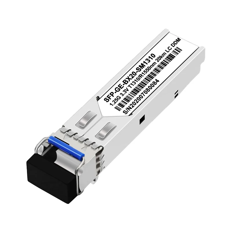
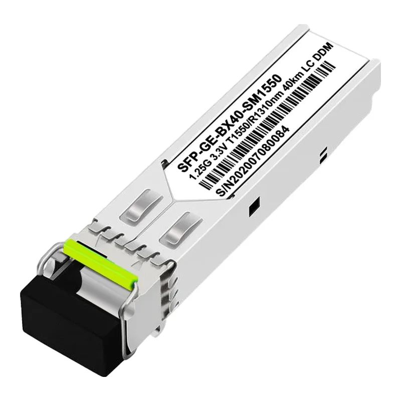
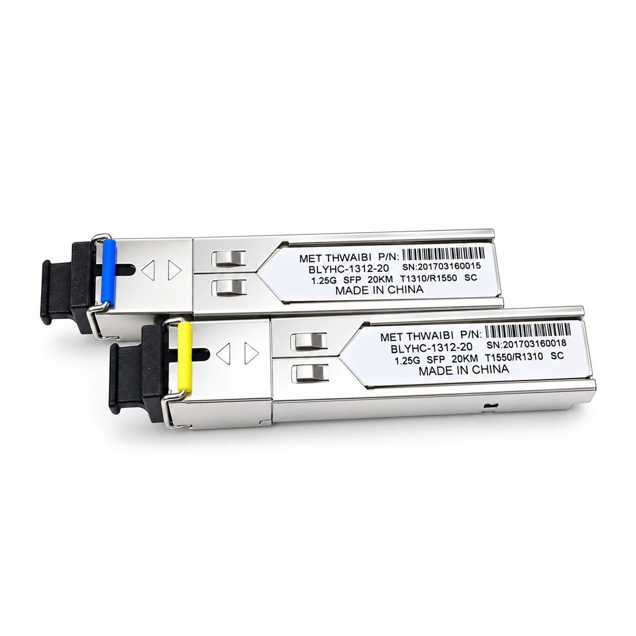
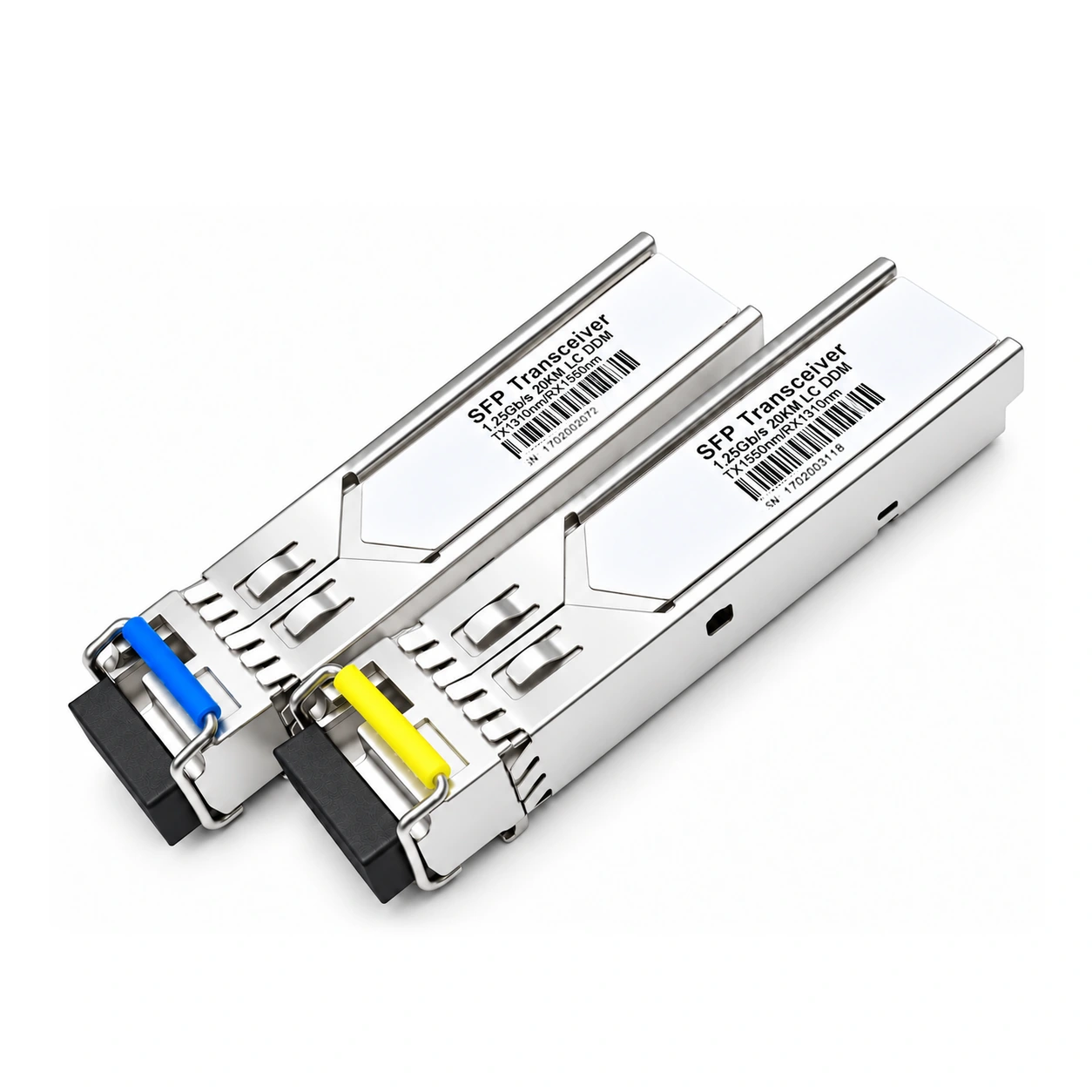
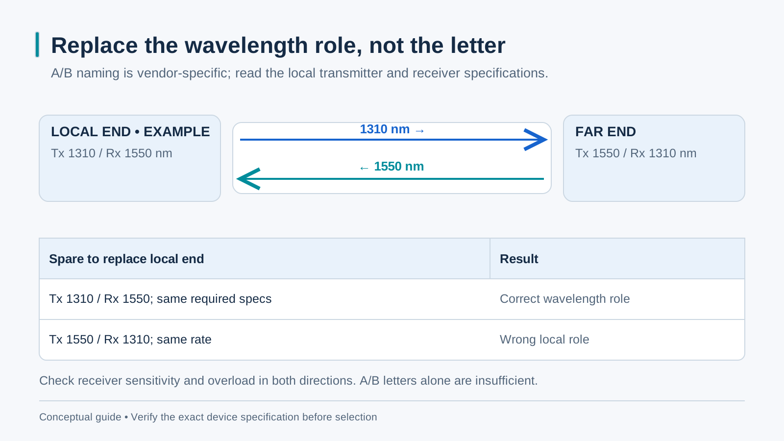
A BiDi module transmits and receives on different wavelength bands over one strand. For an illustrative TX1310/RX1550 endpoint, the partner must transmit within its receive band and receive the local transmit wavelength. A/B letters are vendor labels, not universal definitions. Verify the actual wavelengths, rate and optical specifications at both ends.
The wavelength pairing table
Build the pairing table from the current specifications of the exact modules being ordered. Some BiDi families use 1310/1550 nm and others use different bands, including 1310/1490 nm. Do not assume every distance or connector variant shares one scheme. Dual-fiber LX-type optics use separate TX and RX strands and are not interchangeable with a single-fiber BiDi endpoint.
Mistake 1: A to A (or B to B)
Two modules with the same TX/RX role generally do not form the intended complementary pair. Read the actual wavelength specifications rather than relying only on A/B labels. Confirm the optical standard, rate and host support as well. When correcting a pairing mistake, replace the endpoint needed to create the approved complementary pair.
Mistake 2: mixing distance classes on a long link
Different reach classes are not automatically compatible. Check the transmit and receive wavelength bands, rate, minimum TX power, sensitivity and maximum receiver input in both directions, along with vendor support. Size the link from measured loss and rated reach. A longer-reach or higher-power optic can need attenuation on a short or low-loss route.
Mistake 3: forgetting the far end of a converter pair
A converter link needs one module per end, so a pair order is two modules — and the A/B split runs across the link, not doubled inside one rack. When a crew installs two B's at the exchange because both arrived in the same box, the remote site stays unreachable for a day. Ordering rule: every BiDi purchase is written as 1 × A + 1 × B per link, line item by line item. Stocking rule: keep A and B spares in equal numbers, in the same drawer.
Labeling that survives five years
Label each endpoint with the link name, local TX/RX wavelengths, module part number and slot. Record both ends in the node sheet, along with received optical power in dBm and path loss or margin in dB at commissioning. Consistent route labels and a matched spare pair help a technician identify the correct replacement.
Five-minute diagnosis of a dead BiDi link
Read both module specifications and host settings first, then check received power at both ends where diagnostics are available. Inspect and clean connectors safely and compare readings with the specific optic limits. Replace a suspected module with a known-good spare of the same required local TX/RX role, rate and optical specification. The complementary role belongs at the remote end; swapping the local role can create a new mismatch.